
NOTA: La imagen
mostrada es tomada de la versión en Inglés del Software del PoScope.
ITSS,
Ltda. entrega a todos sus compradores en Latinoamérica la versión
traducida al Español del Software de PoScope y del Manual del Usuario.
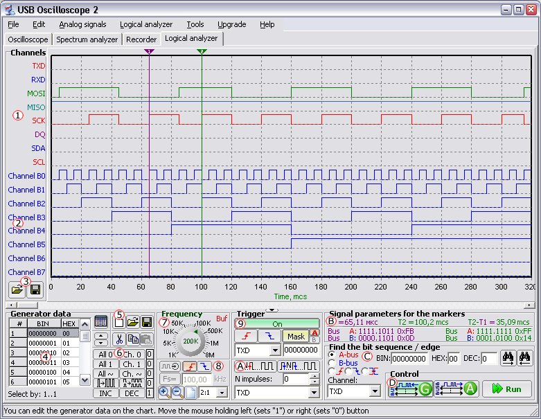
La figura muestra la ventana principal del programa cuando se está
operando en modo de Analizador Lógico. Elementos como los marcadores,
las barras de desplazamiento y el panel de configuración de la
frecuencia de muestreo (base de tiempo) son similares al elemento
correspondiente en el modo de Osciloscopio. A continuación se explican los demás
elementos de la ventana.
A la izquierda del área de trabajo hay un panel que contiene los
nombres de todos los dieciséis (16) canales, los cuales están
divididos funcionalmente en dos (2) buses. Los primeros ocho canales
están realcionados con el Bus A 1 y los siguientes ocho canales están relacionados con el Bus B 2.
Los canales del Bus A (en adelante llamados "Bus A") son siempre usados
como un Analizador Lógico de 8 canales. Loa canales del Bus B (en
adelante llamados "Bus B") pueden ser usados como Generador Lógico de 8
canales o como un Analizador de Espectro adicional, de 8 canales, o
puede estar desactivado. El modo de operación del Bus B es configurado
por los botones correspondientes, en el panel de control D.
Adicionalmente, el color y el nombre de cada canal puede ser cambiado
al seleccionarlo con el mouse (click izquierdo) y trabajando en la
ventana de "Configuración de Canal" que se presenta.
Para cambiar el nombre de un canal se debe
incluir en nuevo nombre en el campo "Nombre del Canal" ("Channel
name"). Para cambiar el color de un canal se debe hacer "click
izquierdo" en la lista de selección llamada "Color del Canal" ("Channel
Color") y luego se selecciona el color deseado. Si no encuentra el
color deseado, puede seleccionar "Personalizado ..." ("Custom…") y la
ventana estándar de configuración de color aparecerá. Para aplicar
estos cambios, simplemente presione el botón "OK" y para ignorar estos
cambios presione el botón "Deshacer" ("Undo").
Debajo del panel de los "Canales" ("Channels") hay dos botones 3 que permiten abrir y guardar los nombres y colores de los canales a un archivo.

En la parte inferior izquierda de la ventana principal hay un panel "Generador de Datos" ("Generator data") el cual está activo sólo si el Bus B está configurado en el modo de Generador de Lógica de 8 canales. Como el nombre del panel lo indica, está diseñado para configurar (crear) los gráficos de tiempos del generador. En la parte izquierda del panel está la Tabla 4 que contiene los datos de generación en formatos binario y hexadecimal. Los datos en la tabla pueden ser modificados de dos formas: directamente escribiendo los datos, o seleccionando la parte necesaria en la tabla y presionando los botnes relativos de generción de gráficos de tiempo 6. Para editar una señal inmediatamente, se debe presionar el botón ubicado sobre la esquina superior derecha de la tabla, o haciendo doble-click sobre la tabla. Para seleccionar los datos, se debe presionar el mismo botón, una vez más, o las teclas Ctrl+D. Para seleccionar la porción de datos en la tabla, se debe seleccionar el inicio del rango con "click izquierdo" y luego, manteniendo oprimido el botón izquierdo del mouse, mover el mouse hasta el final del rango deseado. Si el rango deseado es muy grande, se puede seleccionar el inicio del rango con "click izquierdo", y manteniendo la tecla Shift oprimida, desplazarse con la barra de desplazamiento vertical hasta el fin de rango deseado. Para seleccionar todas las celdas de la tabla, se puede oprimir la combinación de teclas Ctrl+A.
También hay una fila de botones 5 en el panel de generación de datos, que permiten limpiar los datos de la tabla, leer los datos de un archivo, o guardar los datos de la tabla a un archivo, copiar o cortar los datos de la tabla que están seleccionados y pegar datos del buffer a la tabla.
Las gráficas de tiempo del
generador pueden ser configuradas en la
tabla, o directamente sobre el área de trabajo con el mouse. Para
dibujar la gráfica de tiempo de uno de los canales del generador, es
necesario ubicar el mouse entre las líneas punteadas horizontales,
determinando los límites del canal seleccionado y presionando
cualquiera de los botones del mouse. Si se oprime el botón izquierdo
del mouse la porción del gráfico de tiempo dibujada aceptará el estado
de la unidad lógica, y si se orpime el botón derecho del mouse,
será un cero lógico.
Panel "Frequency" 7 allows setting the sampling frequency (time base). This panel is functionally similar to other time base settings panels. Exclusion is only that there are several actual submodes of the logical analyzer, which are automatically selected depending on the set time base:
- 4…8 MHz - buffer size is just 128 bytes, only one bus А is functioning, triggering by mask is only for the bus А (ignoring don't care condition), triggering by edge is only for the channels of the bus B (i.e. you can analyze 8-bit bus and trigger by signals WR, RD and etc.), no pretrigger, no pulse miss. This submode is for analysis of the moderate-speed 8-bit buses that enable triggering for the additional channels.
- 2…2.67 MHz - buffer size is equal to 1160 bytes, only bus А is functioning, triggering by mask is only for the bus А (considering don't care condition), triggering by edge is only for the channels of the bus B (i.e. if required triggering by edge for one of the channels of the bus A the cord of the bus B is to be connected as well, that is inconvenient), fixed pretrigger buffer length equal to 8 bytes, no pulse miss. This submode is for analysis of the low-speed 8-bit buses that enable triggering for the additional signals and small pretrigger.
- from 1 MHz and lower (when buffer reading) - buffer size is equal to 1544 bytes, all the modes are available (analyzer, analyzer + generator, analyzer + analyzer). All the types of triggering are active and there is pulse miss, adjustable pretrigger buffer depth 8 to 120 bytes. External clocking (triggering) option is also added. This submode is for general purpose, you can analyze both low-frequency data buses and bit-sequence interfaces (just analyze but acquire data) and logical generator is active in this submode as well.
- from 500 KHz and lower (when pipe reading) - buffer size is equal, limited by the computer memory. It is not recommended to set the buffer size more than several Мbytes as it is extremely inconvenient to analyze such long signals. One channel show will take memory that 16 (2*SizeOf(double)) times more than the buffer size, i.e. to show the whole bus it requires memory that 16*8 = 128 times more, providing that the waveform value changes for every sample capture. If there are pauses or pulses longer than one sample capture then they are coded with just 16 bytes (2*SizeOf(double)). When pipe reading the bus А is only active, all the types of triggering are available, adjustable pretrigger buffer depth is 1 to 99% of the given buffer depth. Option of external clocking (triggering) is also added. This submode is mainly for analysis of interface sequence. When using the computer memory as a waveform buffer you can record very long waveform portions for its subsequent analysis.
There are elements 8 below the sampling frequency settings knob that ensure turning on the external clocking (triggering) mode. With these elements you can select the edge of external clock signal to perform sample capture. External clock signal frequency can be set both by knob or when inputting the exact frequency value in the field Fs. External clock signal frequency value is setting only for the correct show of charts in the time base.
It makes sense to explain the point of external clocking application by example:
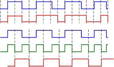
The
figure displays the following binary waveforms:
• blue color - input
• red color - received (shown) signal
• green color - external clock signal
In
the first case the internal sampling frequency is used, e.g. 1 MHz
where the point of waveform sample capture is shown with the dash lines
in 1 mcs. Input frequency is APPROXIMATELY equal to 250 KHz, i.e. 4
times less than the sampling frequency that is good enough. As is
evident from two upper charts the first pulse and pause when receiving
signal completely correspond to input. The next pulse will be almost by
50% longer because in the point of sample capture the input was at the
peak logical level for just several fractions of mcs longer than for
the first pulse. As is evident from the figure as the input frequency
is APPROXIMATELY equal to 250 KHz, i.e. there is a minor pulse and
pause time jitter and the resulting signal is sufficiently distorted
(it is necessary to consider if input parameters are to be correctly
measured).
In the second case the external clocking is used. As
is evident from the figure the input level changes as to the
rising-edge of clock signal and the falling edge of clock signal is
approximately at the midlevel of input pulse or pause and it follows
that it is expedient to set clocking as to the falling edge. The point
of waveform sample capture is shown with the dot lines, which concurs
with the falling edge of clock signal. As is evident from the figure
this signal completely corresponds to input except for bias for a half
of period of clock signal, which has no influence.
Based upon
this information it may be concluded that given external clock signal
synchronous with the input (generally it is a common practice for
protocol sequence) "value" of each sample capture increases. So, when
internal clocking there were 16 sample captures and minor signal
distortion and when external clocking there were only 8 sample captures
and this signal completely corresponds to input. "Value" of each sample
capture increases because the sample capture is performed within the
"correct" point in time to be determined by external clock signal.
Moreover, if we suppose that instead of 4 input pulses we will receive
only 2 input pulses and 4 clock ones (e.g. in default of exchange) then
when internal clocking we will anyway receive 16 sample captures, which
half is out of exchange and at the same time when external clocking we
will receive only 2 "correct" sample captures. For the external
clocking functions the microcontroller hardware is used about which the
external clock signal can be fed only to the channels of the bus B,
i.e. when applying the bus B as 8-channel generator the external
clocking is inaccessible.
All the triggering controls (called trigger for digital signals) except
for the markers are positioned on the panel "Trigger" 9.
On/Off button allows turning on and off triggering below which there
are the triggering operation option buttons: with rising or falling
edge of the selected channel signal or triggering with mask. There is
the dropdown list below the triggering signal edge option buttons that
is to select the triggering source channel only by edge. To the right
of the mask triggering settings buttons there are two small select bus
buttons, to which the given mask will be applied at triggering. Mask is
set in the filed positioned below the mask triggering settings button
in binary format at that the symbol 'x' or '-' means the don't care
condition of the corresponding channel. In the bottom half of the
triggering panel there are the elements determining necessity to skip a
set number of pulses A.
Miss pulses will be active only if triggering is on. To start the miss
pulses mode it is necessary to press one of the buttons determining the
pulse start if no button is pressed the miss pulses mode is failed. In
the field "N pulses" upon meeting triggering condition the required
number of missing pulses is set and in the dropdown list positioned
beneath the panel the channel is selected for which calculating and
missing the given pulses number will be performed. It is expedient to
use the miss pulses mode if concatenation mode is off.
On the panel "Signal parameters below markers" B
similar to operating in the oscilloscope mode the position of each
marker on the time base and status of each bus below the marker are
shown. Markers time lag is also calculated.
Panel C
is to find the bit sequence/edge on one of two buses. Before you start
it is necessary to select the bus/channel to find and set the bit
sequence/edge in binary, hexadecimal or decimal format. To start
finding it is necessary to press one of the search buttons. If the set
bit sequence/edge has not been found then the marker 1 will be
automatically shifted to it otherwise the message window with
information about no set bit sequence/edge to found will open.
On the control panel D
there are the buttons determining the operation mode of the bus B.
Button with G icon moves the bus B into the operation mode of logical
generator and the button with A icon - into the mode of additional
8-channel analyzer. If no buttons are pressed then the bus B is deemed
off. On the control panel there is also the start single measurement
button. It is necessary to note that if the bus B is used in the
logical generator mode and triggering is on then the data will be fed
to the generator bus upon completing the triggering event but not
immediately upon pressing the Run button.
 |
ITSS, Ltda.
Carrera 54 # 123A - 49 Bogotá, D. C. Colombia - Suramérica Teléfono: +(57-1) 617-6651 E-mail: poscope < at> itss.com.co |